
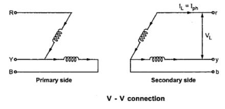
As seen previously in connection of three single phase transformers that if one of the transformers is unable to operate then the supply to the load can be continued with the remaining tow transformers at the cost of reduced efficiency. The connection that obtained is called V-V connection or open delta connection.
Consider the Fig. 1 in which 3 phase supply is connected to the primaries. At the secondary side three equal three phase voltages will be available on no load.
 |
| Fig. 1 |
The voltages are shown on phasor diagram. The connection is used when the three phase load is very very small to warrant the installation of full three phase transformer.
If one of the transformers fails in ∆ - ∆ bank and if it is required to continue the supply eventhough at reduced capacity until the transformer which is removed from the bank is repaired or a new one is installed then this type of connection is most suitable.
When it is anticipated that in future the load increase, then it requires closing of open delta. In such cases open delta connection is preferred.
Key point : It can be noted here that the removal of one of the transformers will not give the total load carried by V - V bank as tow third of the capacity of ∆ - ∆ bank.
The load that can be carried by V - V bank is only 57.7% of it. it can be proved as follows.
 |
| Fig. 2(a) |
 |
| Fig. 2(b) |
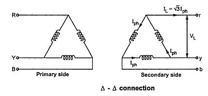
It can be seen from the Fig. 2(a)
∆ - ∆ capacity = √3 VL IL = √3 VL (√3 Iph )
∆ - ∆ capacity = 3 VL Iph ............(i)
It can also be noted from the Fig. 2(b) that the secondary line current IL is equal to the phase current Iph.
V- V capacity = √3 VL IL = √3 VL Iph ...............(ii)
Dividing equation (ii) by equation (i)


Thus the three phase load that can be carried without exceeding the ratings of the transformers is 57.5 percent of the original load. Hence it is not 66.7 % which was expected otherwise.
The reduction in the rating can be calculated as {(66.67 - 57.735)/(57.735)}x 100 = 15.476
Suppose that we consider three transformers connected in ∆ - ∆ fashion and supplying their rated load. Now one transformer is removed then each of the remaining tow transformers will be overloaded. The overload on each transformer will be given as,

Key point : This overload can be carried temporarily if provision is made to reduce the load otherwise overheating and breakdown of the remaining tow transformers would take place.
The limitation with V -V connection are given below :
- The average p.f. at which V- V bank is operating is less than that with the load . This power p.f is 86.6 % of the balanced load p.f.
- The tow transformers in V -V bank operate at different power factor except for balanced unity p.f .load.
- The terminals voltages available on the secondary side become unbalanced. This may happen eventhough load is perfectly balanced.
Thus in summary we can say that if tow transformers are connected in V - V fashion and are loaded to rated capacity and one transformer is added to increase the total capacity by √3 or 173.2 %. Thus the increase in capacity is 73.2 % when converting from a V - V system to a ∆-∆ system.
With a bank of tow single phase transformers connected in V-V fashion supplying a balanced 3 phase load with cosΦ asp.f., one of the transformer operate at a p.f. of cos (30-Φ) and other at cos (30+Φ). The powers of tow transformers are given by,
P1 = KVA cos (30-Φ)P2 = KVA cos (30+Φ)
Example :
A ∆ -∆ bank consisting of three 40 KVA, 2300/230 V transformers supplies a load of 80 KVA. If one transformer is removed, find for the resulting V - V connection
i) KVA load carried by each transformerii) percent of rated load carried by each transformer
iii) total KVA rating of the V - V bank
iv) ratio of the V - V bank to ∆ - ∆ bank transformer ratings
v) percent increase in load on each transformer when bank is converted into V - V bank.
Solution
i) KVA load carried by each of the transformer is calculated as,
(Total KVA load in V - V bank)/(KVA load carried per transformer) = √3
KVA load carried per transformer = (Total KVA load)/√3 = 80/ √3 = 46.18 KVA
ii) Percent of rated load carried by each transformer = (KVA / transformer)/(KVA rating / transformer)
= 46.18/40 = 115.45%
iii) KVA rating of V - V bank = (3 x 40) x 0.577 = 120 x 0.577 = 69.24
iv) (V -V rating)/(∆ - ∆ rating) = 69.24/120 = 0.577 or 57.7%
v) Load supplied by each transformer in ∆ - ∆ bank = 80/3 = 26.66 KVA
% increase in load supplied by each KVA load/transformer in transformer
= (V- V bank)/(KVA load / transformer in ∆ - ∆ bank) = 46.18 / 26.66 = 1.732 or 173.2%
Related articles :
- The T-T connection for 3-Phase Transformer
- Conversion From Three Phase to Tow phase (Scott Connection)
- Three Phase to Six Phase Conversion
Sponsored links :
Excellent Explanation...!!
ReplyDeleteSome of your diagram in 3 phase t/f is wrong ....please correct it sir
ReplyDeleteThrough out this post and other related posts the author uses the word "tow" but it should be "two". It may be just a typo but it had me trying to find out what "tow" meant before it dawned on me that it was probably just a typo.:-)
ReplyDeleteGood information. very well written. keep posting.
ReplyDeleteSMPS Transformer Manufacturer in India | Toroidal Transformer in India